Advanced Macromolecular Preparation Workflow
This example provides a walk-through of the steps taken by SPRUCE to go from an asymmetric unit of an X-ray crystallography experiment to a model-ready design unit. The system being prepared is a structure of the DNA gyrase using the PDB code: 5CDO.
An example script to create a OEDesignUnit can be found at
Code Example
See also
Spruce Theory documentation
Inputs
The data required for Spruce to prepare a macromolecular system is:
A structure file: preferably MMCIF but PDB is also supported.
We recommend reading the files using the SpruceDefault read flavors for these file formats. See more in this example: How to Correctly Read a PDB File.
SSBOND and LINK records are read. If the bonds that are read pass some sanity checks, they are applied to the structure if not automatically perceived by the molecule reader.
Metadata about the sequence and any bound small molecules (heterogens). This can be provided in the metadata/header sections of PDB or MMCIF files. Alternatively, the information can be provided using
OEStructureMetadatafor applications and floes, the content of which can be stored in a JSON file format. The metadata required is:- Experimental and space group information
CRYST1
EXPDAT
- Title information
HEADER
- Revision information
REVDAT
- Biological unit information
REMARK 300
REMARK 350
- Sequence information (using the PDB metadata notation; equivalent keys in MMCIF are also considered)
SEQRES
SEQADV
DBREF, DBREF1/DBREF2
MODRES
- Refinement information to be used for Iridium classification
EXPDTA
REMARK 3 (if available)
In the example walk-through here, all of the metadata is contained in the PDB file.
However, we will use a custom metadata file for the heterogen to
augment the bond order and valence states of one of the heterogens.
Heterogen information can be provided using the OEHeterogenMetadata class
within the OEStructureMetadata class.
- Heterogen information
Title/residue name, such as ATP
Optionally a corporate ID, such as OE123456
SMILES, used for automated tautomer generation with OEQuacpac
OEGetReasonableTautomersfunctionA list of tautomers if the user wants to provide externally generated tautomers.
Filtering and Standardization
OESpruceFilter performs a standardization and a filter check before preparing this structure (OESpruceFilterOptions), which includes:
Fixing backbone atom states
OEFixBackboneFixing bonds to metal
Checking electron density overlap
Checking sequence alignment
Reordering the atoms into PDB order
OEPDBOrderAtomsIncluding standard residue perception for PDB files and Chem Comp residue perception for CIF files
Fixing invalid covalent bonds
Fixing problematic residue namespace
Fixing chain IDs
Preparation for 5CDO builds missing OXT atoms when fixing the backbone:
Debug: Built missing OXT atom in backbone of terminal residue LEU 490   A 1
Debug: Built missing OXT atom in backbone of terminal residue LEU 490   C 3
Debug: Built missing OXT atom in backbone of terminal residue LEU 490   R 7
Debug: Built missing OXT atom in backbone of terminal residue LEU 490   T 9

Debug: Built missing OXT atom in backbone of terminal residue VAL 638   B 2
Debug: Built missing OXT atom in backbone of terminal residue VAL 638   D 4
Debug: Built missing OXT atom in backbone of terminal residue VAL 638   S 8

Debug: Built missing OXT atom in backbone of terminal residue ARG 252   R 7
Debug: Built missing OXT atom in backbone of terminal residue ALA 637   U 10
Generating the Biological Unit
Generation of biological units from asymmetric units is done by reading the _pdbx_struct_assembly, _pdbx_struct_assembly_gen, and _pdbx_struct_oper_list categories in the MMCIF file.
The asymmetric unit contains two biological units as noted in the MMCIF header:
loop_
_pdbx_struct_assembly.id
_pdbx_struct_assembly.details
_pdbx_struct_assembly.method_details
_pdbx_struct_assembly.oligomeric_details
_pdbx_struct_assembly.oligomeric_count
1 author_defined_assembly ? hexameric 6
2 author_defined_assembly ? hexameric 6
In the case of the PDB file, generation of biological units from asymmetric units is done by reading the REMARK 300 and 350 in the header.
REMARK 300 BIOMOLECULE: 1, 2
REMARK 300 SEE REMARK 350 FOR THE AUTHOR PROVIDED AND/OR PROGRAM
REMARK 300 GENERATED ASSEMBLY INFORMATION FOR THE STRUCTURE IN
REMARK 300 THIS ENTRY. THE REMARK MAY ALSO PROVIDE INFORMATION ON
REMARK 300 BURIED SURFACE AREA.
By default, Spruce uses the author-generated remarks and prefers them over the software-generated remarks. Generating the biological unit from the asymmetric unit can take various forms, including symmetry operations to generate the correct biological form specified.
In the event the end user knows the biological unit of interest, and it is different from the author- or software-provided one, a reference structure can be provided that will be used along with the space group information to generate the desired biological unit(s).
Read more in the Biological Unit section and the toolkit API OEExtractBioUnits.
In this specific case, the biological units are generated by splitting the asymmetric unit.
loop_
_pdbx_struct_assembly_gen.assembly_id
_pdbx_struct_assembly_gen.oper_expression
_pdbx_struct_assembly_gen.asym_id_list
1 1 A,B,C,D,E,F,M,N,O,P,Q,R,S,T,U,V,W,HA,IA,JA,KA,LA,MA
2 1 G,H,I,J,K,L,X,Y,Z,AA,BA,CA,DA,EA,FA,GA,NA,OA,PA,QA,RA,SA
#
_pdbx_struct_oper_list.id                   1
_pdbx_struct_oper_list.type                 'identity operation'
_pdbx_struct_oper_list.name                 1_555
_pdbx_struct_oper_list.symmetry_operation   x,y,z
_pdbx_struct_oper_list.matrix[1][1]         1.0000000000
_pdbx_struct_oper_list.matrix[1][2]         0.0000000000
_pdbx_struct_oper_list.matrix[1][3]         0.0000000000
_pdbx_struct_oper_list.vector[1]            0.0000000000
_pdbx_struct_oper_list.matrix[2][1]         0.0000000000
_pdbx_struct_oper_list.matrix[2][2]         1.0000000000
_pdbx_struct_oper_list.matrix[2][3]         0.0000000000
_pdbx_struct_oper_list.vector[2]            0.0000000000
_pdbx_struct_oper_list.matrix[3][1]         0.0000000000
_pdbx_struct_oper_list.matrix[3][2]         0.0000000000
_pdbx_struct_oper_list.matrix[3][3]         1.0000000000
_pdbx_struct_oper_list.vector[3]            0.0000000000
REMARK 350 COORDINATES FOR A COMPLETE MULTIMER REPRESENTING THE KNOWN
REMARK 350 BIOLOGICALLY SIGNIFICANT OLIGOMERIZATION STATE OF THE
REMARK 350 MOLECULE CAN BE GENERATED BY APPLYING BIOMT TRANSFORMATIONS
REMARK 350 GIVEN BELOW.  BOTH NONCRYSTALLOGRAPHIC AND
REMARK 350 CRYSTALLOGRAPHIC OPERATIONS ARE GIVEN.
REMARK 350
REMARK 350 BIOMOLECULE: 1
REMARK 350 AUTHOR DETERMINED BIOLOGICAL UNIT: HEXAMERIC
REMARK 350 APPLY THE FOLLOWING TO CHAINS: A, B, C, D, E, F
REMARK 350   BIOMT1   1  1.000000  0.000000  0.000000        0.00000
REMARK 350   BIOMT2   1  0.000000  1.000000  0.000000        0.00000
REMARK 350   BIOMT3   1  0.000000  0.000000  1.000000        0.00000
REMARK 350
REMARK 350 BIOMOLECULE: 2
REMARK 350 AUTHOR DETERMINED BIOLOGICAL UNIT: HEXAMERIC
REMARK 350 APPLY THE FOLLOWING TO CHAINS: R, S, T, U, V, W
REMARK 350   BIOMT1   1  1.000000  0.000000  0.000000        0.00000
REMARK 350   BIOMT2   1  0.000000  1.000000  0.000000        0.00000
REMARK 350   BIOMT3   1  0.000000  0.000000  1.000000        0.00000
Now we have two biological units one with chains A, B, C, D, E, F, and the other with chains R, S, T, U, V, W.
Generating Packing Residues
Packing residues are by default generated by using the crystallographic information to build the crystal lattice
around each biological unit and extracting the potentially relevant pieces close to the biological unit.
The packing residues are included in the OEDesignUnit object for visualization, and they
are also used in determination of the Iridium category for a given biological unit.
Enumerating Alternate Locations
By default, SPRUCE enumerates all alternate locations.
It has two behaviors, one pairing all A locations together, all B locations together, and so on, and another where
it picks the primary alternate location based on occupancy and mixes and matches in each alternate location cluster. See
the OEAltLocationFactory class.
In this specific case, there are three residues with alternate locations, two in chain A and one in chain R. Since each of these chains are in separate biological units, an A and a B form are generated for each of the biological units.
ATOM   1302  N  N      A ARG A  1  84  ? 39.022  -34.720 51.558  0.50 28.55  ? 92   ARG A N      1
ATOM   1303  N  N      B ARG A  1  84  ? 39.030  -34.712 51.565  0.50 28.56  ? 92   ARG A N      1
...
ATOM   4046  N  N      A ARG A  1  264 ? 34.135  -51.092 43.755  0.50 46.45  ? 272  ARG A N      1
ATOM   4047  N  N      B ARG A  1  264 ? 34.162  -51.078 43.762  0.50 46.44  ? 272  ARG A N      1
...
ATOM   23895 N  N      A ARG G  1  114 ? 70.262  -22.784 -8.389  0.50 30.89  ? 122  ARG R N      1
ATOM   23896 N  N      B ARG G  1  114 ? 70.284  -22.755 -8.432  0.50 30.91  ? 122  ARG R N      1
...
ATOM   1302  N  AARG A  92      39.022 -34.720  51.558  0.50 28.55           N
ATOM   1303  N  BARG A  92      39.030 -34.712  51.565  0.50 28.56           N
...
ATOM   4046  N  AARG A 272      34.135 -51.092  43.755  0.50 46.45           N
ATOM   4047  N  BARG A 272      34.162 -51.078  43.762  0.50 46.44           N
...
ATOM  23901  N  AARG R 122      70.262 -22.784  -8.389  0.50 30.89           N
ATOM  23902  N  BARG R 122      70.284 -22.755  -8.432  0.50 30.91           N
...
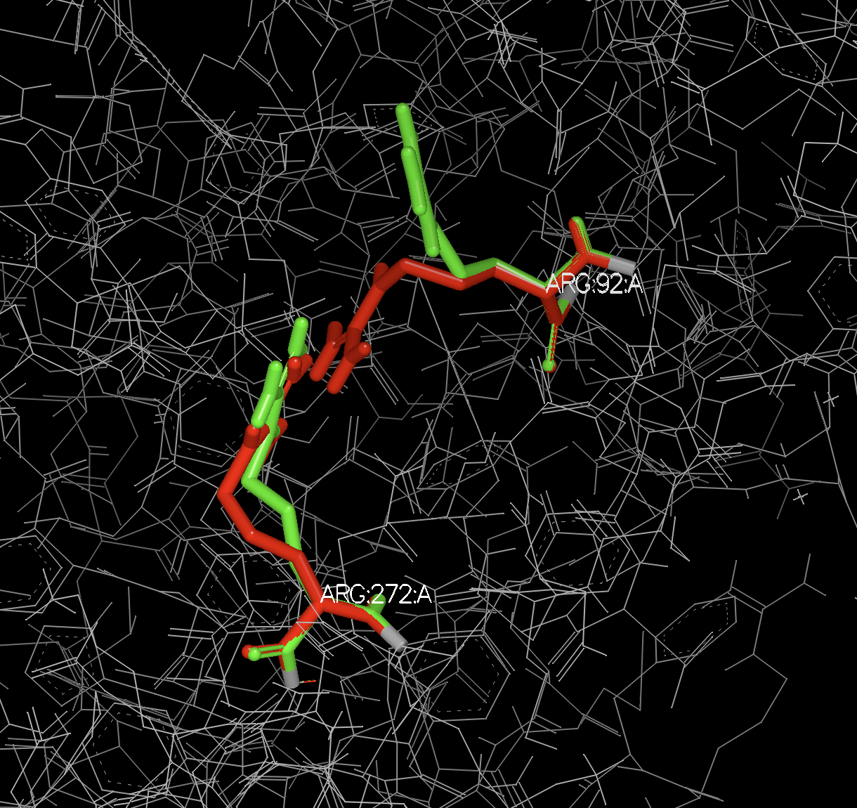
Figure 1. Alternate locations A and B of Arg 92 and 272 in chain A.
Componentizing the System
Spruce next splits the system into components. It does so for various reasons, but mainly to make it easier for end users and downstream applications to extract the relevant parts for modeling. An example would be to exclude excipients when doing subsequent modeling.
The available list of components can be found in the OEDesignUnitComponents namespace.
There are several control parameters for ligand detection. The default parameters generally work very well, but sometimes will need user intervention.
In this specific instance, we focus on the biological unit composed of chains A, B, C, D, E, F. The components being filled are:
protein
nucleic
solvent
metals
counter_ions
packing_residues
excipients
other_ligands
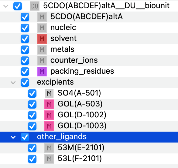
Figure 2. Initial componentization of the biological unit.
The A and B forms of the alternate location enumeration are componentized identically. The unit comprised of chains R, S, T, U, V, W is componentized similarly, but that is not always the case.
Note
There are no binding sites, ligands, or cofactors assigned at this stage. That is done at a later stage when sites in the system are enumerated (Enumerating Sites / Pockets). The potential ligands and cofactors are stored in the other_ligands and metals components for the time being; there can also be an other_cofactors component, depending on the nature of the cofactors.
Building Missing Pieces
Spruce will attempt to build missing pieces that were not observed in the experimental record.
Note
Built residues are styled with a specific color scheme, making built items easy to see in 3D.
Building Missing Side Chains
For the biological unit comprising of chains A, B, C, D, E, F, there were 31 residues that were missing side chains.
Spruce builds these using built-in rotamer libraries OERotamerLibrary and OEBuildSidechains.
Debug:    Residue: ILE 9   A 1
Debug:    Residue: GLU 11   A 1
Debug:    Residue: ARG 231   A 1
Debug:    Residue: ARG 258   A 1
Debug:    Residue: LYS 284   A 1
Debug:    Residue: ARG 299   A 1
Debug:    Residue: LYS 310   A 1
Debug:    Residue: ASP 311   A 1
Debug:    Residue: LYS 405   A 1
Debug:    Residue: GLN 413   A 1
Debug:    Residue: LYS 416   A 1
Debug:    Residue: LEU 490   A 1
Debug:    Residue: LYS 417   B 2
Debug:    Residue: LYS 424   B 2
Debug:    Residue: ARG 450   B 2
Debug:    Residue: LYS 581   B 2
Debug:    Residue: LYS 607   B 2
Debug:    Residue: ARG 12   C 3
Debug:    Residue: ASP 311   C 3
Debug:    Residue: LYS 405   C 3
Debug:    Residue: GLN 413   C 3
Debug:    Residue: LYS 416   C 3
Debug:    Residue: GLU 447   C 3
Debug:    Residue: GLU 475   C 3
Debug:    Residue: LYS 424   D 4
Debug:    Residue: ARG 450   D 4
Debug:    Residue: LYS 497   D 4
Debug:    Residue: GLU 585   D 4
Debug:    Residue: ASN 587   D 4
Debug:    Residue: GLU 593   D 4
Debug:    Residue: LYS 607   D 4
Every built side chain is optimized after being built; in cases where multiple side chains need to be built near each other, they are optimized as a cluster. By default, Spruce will delete water molecules clashing with built side chains, because it is believed that the water positions are likely not correct but an artifact of missing the side chain during crystallographic refinement.
Warning: No rotamer of residue: LYS 497 D 4 passed a clash test. Will check again after minimization
For the Lysine residue 497 in chain D, no known rotamer would fit the local environment, but Spruce is able to find a proper configuration using minimization. In this case, the backbone configuration is not ideal, but a configuration is found that works. It is expected that some backbone rearrangement would happen during a whole system minimization and molecular dynamics simulation.
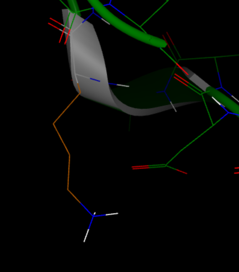
Figure 3. Built side chain of LYS 497 in chain D.
See also
Building Missing Loops and Tails
Spruce uses a knowledge-based loop database to fill in missing gaps; see the LoopDBBuilder overview for more information.
It uses the SEQRES or sequence data provided using OEStructureMetadata to
compare the structure to the known sequence.
The knowledge-based database currently allows building of loops up to 20 residues in length.
For example, in chain R:
Debug: Gap detection sequence alignment:
chainR  -NERNITSEMRESFLDYAMSVIVARALPDVRDGLKPVHRRILYGLNEQGM 49
        |||||||||||||||||||||||||||||||||||||||||||||||||
chain   INERNITSEMRESFLDYAMSVIVARALPDVRDGLKPVHRRILYGLNEQGM 50

chainR  TPDKSYKKSARIVGDVMGKYHPHGDSSIYEAMVRMAQDFSYRYPLVDGQG 99
        ||||||||||||||||||||||||||||||||||||||||||||||||||
chain   TPDKSYKKSARIVGDVMGKYHPHGDSSIYEAMVRMAQDFSYRYPLVDGQG 100

chainR  NFGSMDGDGAAAMRXTEARMTKITLELLRDINKDTIDFIDNYDGNEREPS 149
        ||||||||||||||||||||||||||||||||||||||||||||||||||
chain   NFGSMDGDGAAAMRXTEARMTKITLELLRDINKDTIDFIDNYDGNEREPS 150

chainR  VLPARFPNLLANGASGIAVGMATNIPPHNLTELINGVLSLSKNPDISIAE 199
        ||||||||||||||||||||||||||||||||||||||||||||||||||
chain   VLPARFPNLLANGASGIAVGMATNIPPHNLTELINGVLSLSKNPDISIAE 200

chainR  LMEDIEGPDFPTAGLILGKSGIRRAYETGRGSIQMRSRAVIEER----QR 245
        ||||||||||||||||||||||||||||||||||||||||||||    ||
chain   LMEDIEGPDFPTAGLILGKSGIRRAYETGRGSIQMRSRAVIEERGGGRQR 250

chainR  IVVTEIPFQVNKARMIEKIAELVRDKKIDGITDLRDETSLRTGVRVVIDV 295
        ||||||||||||||||||||||||||||||||||||||||||||||||||
chain   IVVTEIPFQVNKARMIEKIAELVRDKKIDGITDLRDETSLRTGVRVVIDV 300

chainR  RKDANASVILNNLYKQTPLQTSFGVNMIALVNGRPKLINLKEALVHYLEH 345
        ||||||||||||||||||||||||||||||||||||||||||||||||||
chain   RKDANASVILNNLYKQTPLQTSFGVNMIALVNGRPKLINLKEALVHYLEH 350

chainR  QKTVVRRRTQYNLRKAKDRAHILEGLRIALDHIDEIISTIRESDTDKVAM 395
        ||||||||||||||||||||||||||||||||||||||||||||||||||
chain   QKTVVRRRTQYNLRKAKDRAHILEGLRIALDHIDEIISTIRESDTDKVAM 400

chainR  ESLQQRFKLSEKQAQAILDMRLRRLTGLERDKIEAEYNELLNYISELETI 445
        ||||||||||||||||||||||||||||||||||||||||||||||||||
chain   ESLQQRFKLSEKQAQAILDMRLRRLTGLERDKIEAEYNELLNYISELETI 450

chainR  LADEEVLLQLVRDELTEIRDRFGDDRRTEIQL 477
        ||||||||||||||||||||||||||||||||
chain   LADEEVLLQLVRDELTEIRDRFGDDRRTEIQL 482

Found unresolved N-terminal with 1 residues before ASN 10   R 7  , with sequence 'I'
Found 4 residue gap between ARG 252   R 7   and GLN 257   R 7  , with sequence 'GGGR'
As the log summarizes for chain R, a residue was missing at the N-terminal of the protein, and a 4-residue gap was found with the sequence GGGR between residues 252 and 257.
Terminal residues or “tails” are not built by default, partly because the build time for long tails can be significant as the problem is less constrained than a missing gap in the middle of the protein.
When multiple loops need to be built in a structure, Spruce builds the shortest ones first, as they are more geometrically constrained, to avoid a scenario where a loop cannot be built due to the construction of another.
When building a loop, Spruce crops a piece of the existing protein (by default, one residue on either side of the gap) and builds a slightly longer loop. This is in part to avoid the scenario where the anchoring residues are in a bad configuration as a result of crystallographic refinement with missing residues.
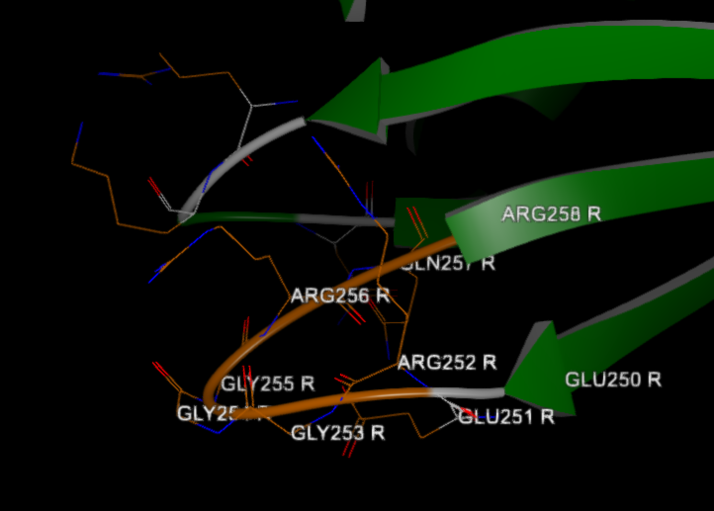
Figure 4. Built loop between Arg 252 and Gln 257 in chain R.
See also
OELoopBuilderOptions class
OERotamerLibrarynamespaceOEStructureMetadata class
Building Capping Groups
If, for some reason, a missing loop/gap could not be built, Spruce adds acetyl (ACE) and N-methyl (NME) capping groups to the terminal residues to avoid having artificial formal charges on the structure. It will, however, not add capping groups to the true biological termini as they are expected to be charged at neutral pH. The information about the true terminals is derived from the SEQRES or provided sequence metadata, similar to the loop.
When building a cap, if the capping group for any reason clashes with other parts of the system (not waters), the residue being capped is instead converted into a capping group. This is to avoid building a system with clashes. The behavior can be modified if desired.
Note
An N-terminal capping group (ACE) is numbered with N-1 to the residue it is capping.
A C-terminal capping group (NME) retains the residue number of the residue it is capping, but an insert code is indented. This is to avoid capping groups and ligands or other features having the same residue number, as it is standard practice to number heterogens following the protein chain using the same chain ID.
See also
Optimizing the Hydrogen Bond Network
Spruce optimizes the hydrogen bond network by adding explicit hydrogens and resolving clashes particularly around the binding site. The process considers the protonation and tautomer states of the components to produce an optimized protein–ligand complex. A specific tautomer state can be provided as part of metadata if it needs to be enforced.
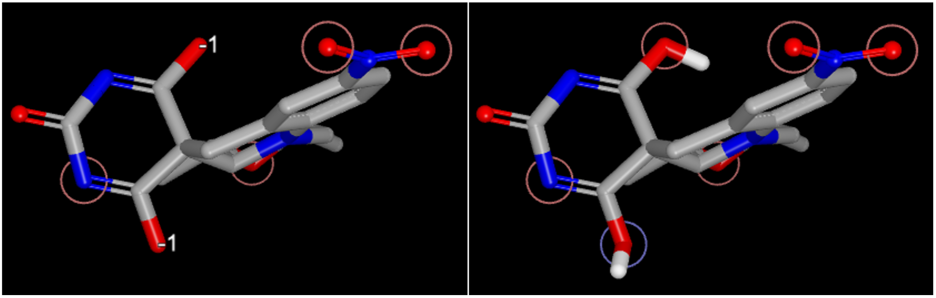
Figure 5. Ligand tautomer state without specified tautomer state (left) and with a specified tautomer (C[C@@H]1C[N@@]2c3ccc(cc3CC4([C@H]2[C@@H](O1)C)C(=NC(=O)N=C4O)O)N(=O)=O, right).
Assignment on Radii and Partial Charges
For more information about the assignment of partial charges to the entire system, please see OEDesignUnitCharges. By default, charges are assigned as follows:
Standard protein residues: OEAmberFF94Charges
Nonstandard protein residues: OEAM1BCCCharges
Nucleic acids: OEMMFF94Charges
Ligands and or any other heterogens in the system (e.g., cofactors): OEAM1BCCCharges
Solvent: uses the SZMAP water model
Excipients: OEMMFF94Charges
Prepared Biological Units (BioDUs)
The above-mentioned stages transformed an asymmetric unit to a biological unit, which was then componentized to generate a prepared biological unit (BioDU).
Enumerating Sites / Pockets
This is the final stage of creating a design unit from a prepared biological unit.
As was noted in the earlier section, there were two potential ligands found and componentized into the other_ligands category. When ligands are detected, Spruce will take the prepared biological unit and generate a design unit for each binding site.
The design unit will now have a binding site defined, and specific styling will be applied to the system. As part of the process, the ligand bound in that binding site will be promoted from the other_ligand category to the ligand category, and cofactors, either from other_cofactors or metals, will be moved to the cofactors category. If a ligand is present, interaction hints are also encoded and stored in the design unit. For more information, see OEInteractionHintContainer.
In the case here, there were two biological units. In the biological units with:
chains A, B, C, D, E, and F, there were two ligands 53L and 53M.
chains R, S, T, U, V, and W, there were two ligands 50M and 53M.
Therefore, for each biological unit, two design units were generated. Note that since there were both an A and a B alternate location form of each biological unit, there are really eight design units in the end.
5CDO(ABCDEF)altA > 53L(F-2101)
5CDO(ABCDEF)altB > 53L(F-2101)
5CDO(ABCDEF)altA > 53M(E-2101)
5CDO(ABCDEF)altB > 53M(E-2101)
5CDO(RSTUVW)altA > 50M(S-6002)
5CDO(RSTUVW)altB > 50M(S-6002)
5CDO(RSTUVW)altA > 53M(W-2101)
5CDO(RSTUVW)altB > 53M(W-2101)
If a ligand was not present, the OEFindPockets algorithm will be employed to attempt to detect potential
binding sites. If multiple sites are found, the BioDU will be enumerated into a DU for each detected site.
Assigning an Iridium Category
The Iridium [Warren-2012] categorization process itself is well explained in the Iridium section, but in short, the Iridium categorization can be used to select between different protein structures if multiple are available for a given target, and also in the event that multiple design units are generated from a single experimental structure. The Iridium category and derived information is stored in OEIridiumData.
In the case here, the enumeration from a single structure file to eight design units gives a little perspective on why this filtering step can be necessary.
There are design units for three different ligands here: 50M, 53M, 53L.
5CDO(ABCDEF)altA > 53L(F-2101), Iridium Category: MT, LaD: 0.85, ASaD: 0.88, DPI: 0.47, POL: false, POAS: false, AltConfs: false, PackRes: false, Excp: false, IrrRFree: false, PossCov: false
5CDO(ABCDEF)altB > 53L(F-2101), Iridium Category: MT, LaD: 0.85, ASaD: 0.88, DPI: 0.47, POL: false, POAS: false, AltConfs: false, PackRes: false, Excp: false, IrrRFree: false, PossCov: false

5CDO(RSTUVW)altA > 50M(S-6002), Iridium Category: MT, LaD: 0.85, ASaD: 0.86, DPI: 0.47, POL: false, POAS: false, AltConfs: false, PackRes: false, Excp: false, IrrRFree: false, PossCov: false
5CDO(RSTUVW)altB > 50M(S-6002), Iridium Category: MT, LaD: 0.85, ASaD: 0.86, DPI: 0.47, POL: false, POAS: false, AltConfs: false, PackRes: false, Excp: false, IrrRFree: false, PossCov: false
For 50M and 53L, there are two forms due to alternate locations for each. The scores are identical and in this case either form is likely okay to use.
5CDO(ABCDEF)altA > 53M(E-2101), Iridium Category: MT, LaD: 0.81, ASaD: 0.85, DPI: 0.47, POL: false, POAS: false, AltConfs: false, PackRes: false, Excp: false, IrrRFree: false, PossCov: false
5CDO(ABCDEF)altB > 53M(E-2101), Iridium Category: MT, LaD: 0.81, ASaD: 0.85, DPI: 0.47, POL: false, POAS: false, AltConfs: false, PackRes: false, Excp: false, IrrRFree: false, PossCov: false
5CDO(RSTUVW)altA > 53M(W-2101), Iridium Category: MT, LaD: 0.74, ASaD: 0.88, DPI: 0.47, POL: false, POAS: false, AltConfs: false, PackRes: false, Excp: false, IrrRFree: false, PossCov: false
5CDO(RSTUVW)altB > 53M(W-2101), Iridium Category: MT, LaD: 0.74, ASaD: 0.88, DPI: 0.47, POL: false, POAS: false, AltConfs: false, PackRes: false, Excp: false, IrrRFree: false, PossCov: false
For 53M, there are four forms: two resulting from different biological units (chains), and two of each of those resulting from alternate locations. The alternate locations forms have identical scores and do not differentiate the forms. However, for the two biological units, the Iridium information is very different even if their overall scores are both MT. In particular, the fraction of ligand atoms covered by the experimental density is 0.81 versus 0.74, and the fraction of active site residue atoms covered by density is 0.85 versus 0.88. In this case, it will likely take a modeler or crystallographer to decide which is the better pose, and in some cases, both should be used for proper modeling.
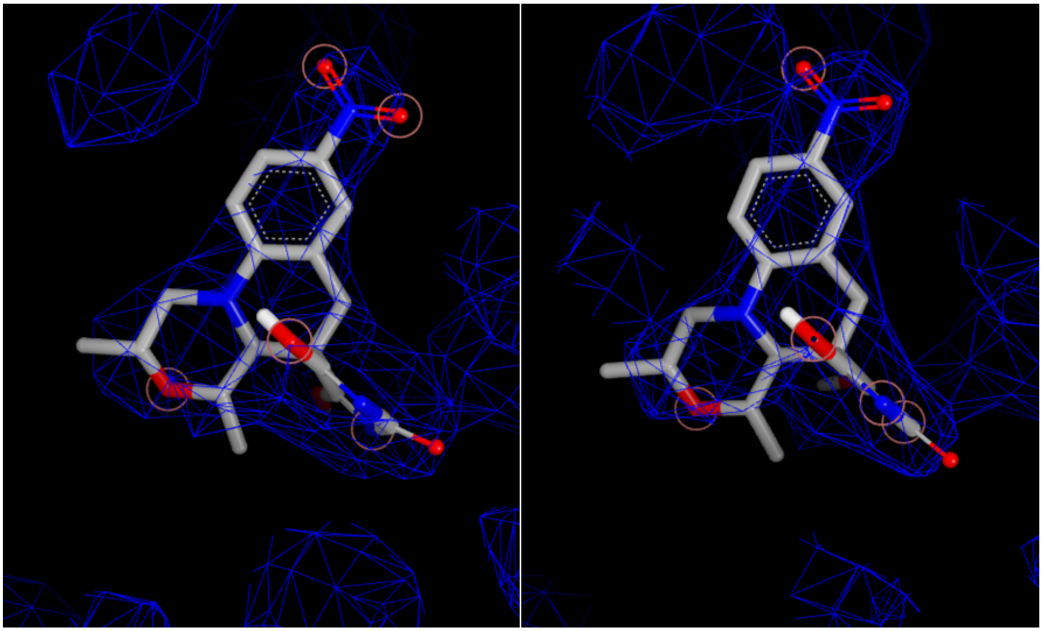
Figure 6. Experimental density and ligand overlap for the two biological units.
Generating a Docking Receptor
The toolkit does not automatically generate a docking receptor, but the SPRUCE application and floe both generate a
docking grid using default settings with the OEMakeReceptor function.
The receptor can later be modified or regenerated with the toolkit or the Make Receptor application if a more custom
approach is desired.
Superposition to a Common Frame of Reference
Spruce is able to superpose molecules and design units onto a common reference
frame using OESuperpose.
If a common reference structure is provided, all generated design units will be superposed to that reference structure.
If a common reference structure is not provided, but each design unit generated is similar to each other (same protein, same binding site),
Spruce will superpose those similar units onto each other.
Design Unit Validation
Spruce validates the design unit using OEValidateDesignUnit. It looks for partial side chains, partial charges,
implicit hydrogens, incorrect terminal residues, heavy atom overlap, and broken chains.