Theory
Spruce TK is used to process PDB or mmCIF files containing the macromolecular structures, resulting from X-ray crystallography, Nuclear Magnetic Resonance (NMR) spectroscopy, or electron microscopy (EM) experiments into molecules usable for molecular modeling. Due to the nature of the experiments and data, some processing is required before use in modeling, such as adding explicit hydrogens and building pieces that were unobserved in the experimental data, yet required to properly simulate the system.
Spruce TK provides a complete preparation workflow to prepare macrocomolecular structures for modeling. Various options are available to control for desired behaviors. Additional metadata can be provided, along with the structural data to improve perception of small molecule (heterogen) bondage and valence states, as well as protein sequence information (if it is not in the structure file already).
Brief Definitions
In order to fully interpret Spruce TK, it is important to first identify some terms. Very brief definitions are provided in this section, followed by more detailed explanations below.
Asymmetric Unit (ASU): The contents of a PDB or mmCIF file from X-ray crystallography containing an asymmetric unit as the output of the experiment.
Biological Unit (BU): Also know as a biological assembly, this is the biologically relevant unit for a protein to use in modeling. For example, the BU is a monomer in Trypsin, but in HIV Protease it is a homo-dimer.
Bio Design Unit (BioDU): This is a prepared biological unit. This is the result of the Spruce preparation from the extracted BU. It is a fully prepared macromolecular system, but a ligand and associated binding site have not yet been identified. A Bio Design Unit (BioDU) is considered an intermediate work product of the final design unit.
Design Unit (DU): As the name indicates, this is an object used for structure-based drug design. It is a specific instance of a BioDU, where a binding site has been identified. If a ligand is present in that binding site, it has been moved into the ligand component; similarly, the cofactor component has been filled in if any are present in the binding site. This data structure can also have an OEReceptor stored on it for the purposes of docking calculations. Most OpenEye tools use DUs rather than BioDUs, as they utilize the binding site and bound ligand information.
Alternate locations (alt locs): X-ray experiments often contain results with atoms occupying more than one configuration (alt location). Crystallographers denote this with a measure of the amount of time an atom occupies a given set of coordinates. A well-resolved atom will have an occupancy of 1.0, meaning that 100% of the time it is in that location. Sometimes, however, the atom exists in two positions—alternate locations—and these appear in the input file with single letter designations and with occupancy < 1.0. Alternate locations are by default enumerated (but only primary can be selected). When these are enumerated, the generated design units will be checked to see if there are alternate locations in the binding site; if not, they are deduplicated at the end of the preparation workflow (this behavior can be turned off). This is to reduce the number of design units generated for a single input file.
Note
For more information about these, there are two worked examples: the simple example and a more advanced example.
Asymmetric Unit
The asymmetric unit (ASU) is the smallest piece of a crystal structure to which symmetry operations can be applied in order
to generate a complete unit cell (the crystal repeating unit). It contains the unique part of a crystal structure [Zardecki-2022].
The ASU may be equivalent to the BU, but often requires manipulation to create a correct BU. Spruce TK can be used to
expand the AU to the BU. The data structure is stored in an OEMolBase.
Biological Unit
In short, the biological unit (BU) is an object that contains the biologically relevant parts of an
ASU that have not been split into various molecular components and are not yet prepped for modeling.
It is the quaternary structure of a protein that is believed to be the main
functional form of the molecule. It can be a single chain or a collection of multiple chains.
The BU may include more than one functional form if it can change under different conditions.
The data structure is stored in an OEMolBase.
For a more detailed explanation of BUs, refer to the Introduction to Biological Assemblies and the PDB Archive.
A BU can be constructed from a single macromolecular structure file, from the metadata, or by using a sequence
alignment to an input reference structure. To extract a BU or set of BUs from an asymmetric unit, one should use the helper
function in Spruce TK called OEExtractBioUnits. The following example shows
how to extract BUs from the metadata.
Using the same function, one can also extract BUs from an asymmetric unit using an input reference protein. The following example shows
how to use OEExtractBioUnits to extract BUs from a given reference.
Biological Design Unit (BioDU)
Spruce extracts and prepares parts of a single BU to create BioDUs. A biological design unit (BioDU)
is a fully prepared macromolecular system considered ready for modeling (generally considered Molecular Dynamics ready). Heterogen components
are componentized into other_ligands, other_cofactors, counter_ions, metals, and so on. Thus, it has all the information required to generate a
design unit, but is not yet focused on a specific binding site and as such does not contain receptor grids required for docking or other actions.
The BioDU has limited usage, as most OpenEye tools require binding sites and their related information.
The data structure is stored in an OEDesignUnit.
BioDUs are only applicable when a user does not need or want a binding site. The primary uses are:
Design Unit
Design unit (DU) is an idea first discussed by Pfizer [Gehlhaar-2022]. The OEDesignUnit class is a technical term
for a specific data structure created to capture all the information in a macromolecular system and is unique to OpenEye.
An OEDesignUnit file format is an oedu.
A DU is a specific instance of a BioDU. It is binding site focused. One BioDU may yield several DUs if there are multiple binding sites. If there are multiple ligands in a BioDU, each will include its own information related to the binding site.
A DU includes among other components:
A protein and/or nucleic acid
Site residues
A bound ligand in the binding site (if present, otherwise apo)
Cofactors in the binding site
Packing residues (if any exist near the site)
Excipients (if any exist near the site)
One can interact with each part of the DU through APIs, which are listed under OEDesignUnit.
Spruce TK Preparation Workflow
Spruce TK provides an end-to-end preparation workflow using the OEMakeDesignUnits API.
Options (see OEMakeDesignUnitOptions and associated options classes) are available to
control for the desired behavior. Metadata (see OEStructureMetadata) can be supplied
to infuse experimental data, like the proper variant sequence, and also to fix common problems reading
from PDB files (e.g., bond order perception). Spruce has a built-in Chemical Components Dictionary matching residue codes to
SMILES, derived from the corresponding entry at the RCSB, but curated to fix improper molecule forms.
The workflow automatically runs through the following steps to produce OEDesignUnit objects.
Biological unit extraction (see
OEExtractBioUnits).Generation of packing residues for visualization of crystal contacts (if the structure is from X-ray).
Assignment or enumeration of alternate locations (see the
OEAlternateLocationOptionnamespace).Separation of the system into components, such as identifying ligands, cofactors, and excipients.
Construction of missing side chains, modeling loops, and capping chain breaks (see
OEBuildSidechains,OEBuildLoops, andOECapTermini).Hydrogen placement and optimization, including searching ligand tautomer states (see
OEProtonateDesignUnit).Assignment of partial charges to the entire system (see OEDesignUnitCharges).
Superposition to a common reference frame (see OEStructuralSuperposition and OESecondaryStructureSuperposition).
Visualization and more of an encoded OEInteractionHintContainer.
Estimation of the model quality using Iridium [Warren-2012], stored in OEIridiumData.
Note
Multiple design units are often produced. This results from multiple biological units generated during step 1, and further expands that set when enumerating the alternate locations in step 3. The Iridium categorization (see Categorization) should be helpful in choosing which (if not all) of the produced units to use in downstream modeling tasks. We find that the Iridium categories are also helpful for managing modeling expectations, having a quality measure of the input data for modeling.
Note
Included with Spruce TK is a large database of loop templates generated by parsing the structures in the public PDB repository pulled from the RCSB. This database is available from db-downloads in a platform-independent format. The SPRUCE loop database is large (~13G) and will take time to download with a good internet connection. When the download is complete, move the file to a convenient location; a network drive is not recommended for performance.
To use it during preparation (OEMakeDesignUnits), set the path in SetLoopDBFilename method on the OELoopBuilderOptions class.
The database can be appended to (or updated) using the LoopDB_Builder utility program that ships with the SPRUCE application. This would be in the event that the user has a collection of internal or proprietary structures, or if specific structures are released to the public PDB between OpenEye updates of the database that are crucial for a given target that is less well described by the existing templates.
Proton Placement and Optimization
Traditionally, most biomolecular structures have been generated with either no
explicit hydrogens or only polar hydrogens. However, having all atoms explicitly
represented and positioned to make appropriate hydrogen bonds is sometimes necessary.
The function OEPlaceHydrogens does this by adding and
placing hydrogens and by “flipping” certain functional groups
(e.g., side chain amides and imidazoles) as required for an optimal hydrogen bonding network.
Spruce TK leverages this functionality, but builds on top of this by taking the
ligand protomer and tautomer states into account in the OEProtonateDesignUnit
function. The function identifies the heterogens (ligands, cofactors, etc.) in the structure and
enumerates their states using the OEGetReasonableTautomers function or
by using user supplied states.
The hydrogen bonding network of the biomolecule is then optimized in the presence of each state
independently, and the most favorable state of the complex is chosen based on interaction energies.
If a binding site holds two heterogens, such as a ligand and a cofactor, and each have multiple tautomer
states, the combinatorial number of states are optimized and evaluated. To do this efficiently,
only the binding site(s) are initially optimized. After selecting the appropriate states of each of
the binding sites, the remaining parts of the system are optimized, keeping these states fixed.
Protein Side Chain Modeling
Amino acid side chains are sometimes missing in protein structures due to low or
missing density from X-ray diffraction crystallography experiments. This can be due
to high flexibility making the assignment of a specific location of the atoms difficult.
However, most molecule simulation software requires a position of these atoms, and the
lack of them can cause incorrect results. Partial side chains are identified with OEGetPartialResidues.
Using OEBuildSidechains, these residues are then divided into groups based
on proximity and side chain orientation. The groups are independently optimized taking into account their local
environment. In each group, the side chains are built and a standard rotamer library from the
OERotamerLibrary namespace is used. For each side chain, the set of rotamers
is evaluated based on an interaction energy with the nearest environment and the most favorable state is
chosen. In the case where multiple residues are being built in a group, an iterative procedure attempts to
find the optimal energy for the entire set of residues. In the event a side chain cannot be built because
poor input geometry causes clashes, the entire cluster is skipped. Water locations that block
side chain rotamers result in those water molecules being deleted (optionally) since their placement is most likely an artifact.
Protein Loop Modeling
Similar to missing side chains above, there are sometimes gaps in protein structures, where the position
of the entire amino acid residues cannot be resolved based on the experimental data.
The function OEBuildLoops is able to build missing gaps (loops). The workflow is illustrated
in the figure below. The function identifies missing loops by comparing the SEQRES section of the
PDB header with the structure using a sequence alignment. The user can optionally input their
own sequence using OESequenceMetadata if the SEQRES in the header is incorrect or missing.
With the gaps identified, the function loops for templates matching the gap, filters them based on the
ability to fit the gap without clashing, and eventually does an optimization of the top candidates
in the local environment before picking the most favorable conformation.
If multiple results are desired, these can be retrieved using OEBuildSingleLoop.
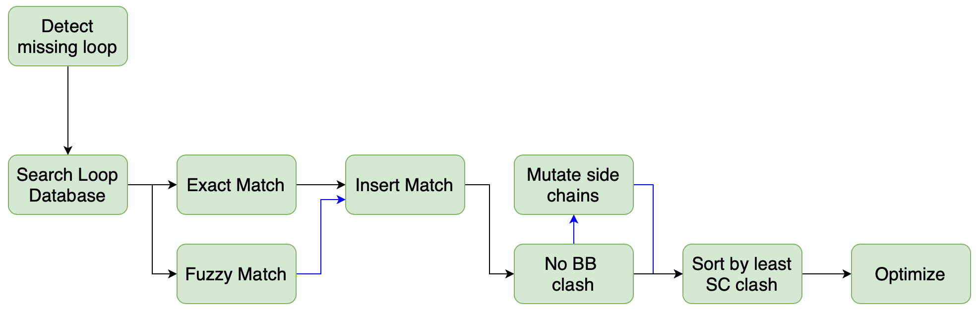
Figure 1. OEBuildLoops: Gaps are searched, filtered, inserted, and evaluated for the best fit.
The loop template database is built using all the structures in the PDB downloaded from the RCSB and can be downloaded from db-downloads.
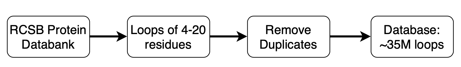
Figure 2. Loop template database. Loops are extracted from the RCSB PDB, deduplicated, compressed, and indexed for easy retrieval.
Protein Superposition
A protein can be structurally superimposed onto a reference protein structure using Spruce TK. Proteins can be superimposed with either atomic coordinates in the OEStructuralSuperposition class, or with secondary structure elements using the OESecondaryStructureSuperposition class.
The OEStructuralSuperposition class can superimpose proteins using any of the following four methods:
The global method (default for OEStructuralSuperposition). This method uses all matching heavy atoms from the reference and fit proteins as the region for performing the superposition calculation (see
OESuperpositionType.Global).The Difference Distance Matrix method. This method calculates the pairwise distance matrix of C-alpha atoms for both the reference and fit proteins, then takes the difference of these two matrices to find the difference distance matrix (DDM).
For a given conformation a, the elements of the distance matrix \(D_{ij}^a\) are the distances between atoms i and j in a molecule,
\[D_{ij}^a = |r_i - r_j|\]where \(r_i\) and \(r_j\) are the Cartesian coordinate vectors of atoms i and j. The elements \(\Delta_{ij}^{ab}\) of the difference-distance matrix for two conformations a and b are
\[\Delta_{ij}^{ab} = D_{ij}^a - D_{ij}^b\]If \(\Delta_{ij}^{ab}\) is positive, the interatomic vector between between i and j in conformation b is contracted with respect to a. Conversely, negative elements of the DDM indicate an expansion of the interatomic vector. The longest contiguous region of the resulting difference distance matrix (DDM) is used for the structural superposition calculation (see
OESuperpositionType.DDM).The weighted-DDM method. This method uses the DDM matrix and calculates Gaussian weighting factors for all matching C-alpha atoms. These Gaussian weights are used as a weighting function in the superposition calculation (see
OESuperpositionType.Weighted).The site residue method. This method uses a set of site residues (given as a set of unique residue strings) as a constraint on the protein superposition. Site residues must be set with the
SetSiteResiduesmember function of the OESuperpositionOptions class (seeOESuperpositionType.Site).
The OESecondaryStructureSuperposition class can superimpose proteins using:
The secondary structure superposition method. This method takes two proteins and performs a structural superposition on them based on the shape overlap of the secondary structure elements of the two proteins.
Note
All structural superposition methods in the OEStructuralSuperposition class have a corresponding score from the sequence alignment that was used to find the matching atoms of both proteins. This score comes from the output of the OESequenceAlignment class, where a larger score indicates a better sequence alignment, and scores below a small threshold (around 200) should be considered a bad alignment.
Note
All structural superposition methods in the OEStructuralSuperposition class have a corresponding RMSD value for superposition that can be loosely associated with the quality of the superposition. The OESecondaryStructureSuperposition class does not have an RMSD value, but instead uses the Tanimoto score from the underlying shape overlap calculation.
How to Correctly Read a Macromolecular File Format (mmCIF/PDB)
Reading a PDB file correctly for use in subsequent modeling tasks can be challenging.
To correctly read a PDB, one must be aware that PDB header information as well as
information about alternate location codes within the PDB file will be lost unless
a specific combination of PDB-centric OEIFlavor`s are used.
Furthermore, the protein itself must be processed by
:oe:cls:`OEAltLocationFactory in order to create a
molecule with all alternate location atoms retained. Spruce handles this for the user,
so they are not handled by this reader. However, for uses other than Spruce, the user
needs to either enumerate the different alternate locations or pick a specific location.
With that in mind, we recommend reading PDB files for use in Spruce TK using
the following pattern as shown in ReadMacromolecule below: