Process X-ray Crystal Structures and Densities
This tutorial demonstrates how to prepare X-ray crystal structures and densities for simulation using the Automated WEMD Simulation and Best Structure Search Guided by Target CryoEM Map and Process X-ray Crystal Structures and Densities Floes.
You will work with two crystal structures of Adenylate Kinase (ADK) from the RCSB:
4AKE: A homodimer crystal structure of the protein in the open state.
1AKE: A monomer crystal structure of the protein in the closed state.
Prepare X-ray Crystal Structures
Prepare the proteins for simulation using the SPRUCE - Protein Preparation Floe.
Navigate to the Floe page to find the floe. From the Utility Floes package, select the SPRUCE - Protein Preparation Floe. Click the “Launch Floe” button to bring up the Job Form.
Inputs: For the PDB Code(s) to Download parameter, enter “1AKE”.
Outputs: Toggle Output All Biological Units to On.
Click the “Start Job” button to begin the floe.
Next, run the SPRUCE - Protein Preparation Floe again for 4AKE. Because the crystal structure for 4AKE does not contain a ligand, an additional parameter is needed.
Unliganded Structure Parameters: Turn the Enumerate Pockets toggle On (otherwise, the floe may fail).
Click the “Start Job” button to begin the floe.
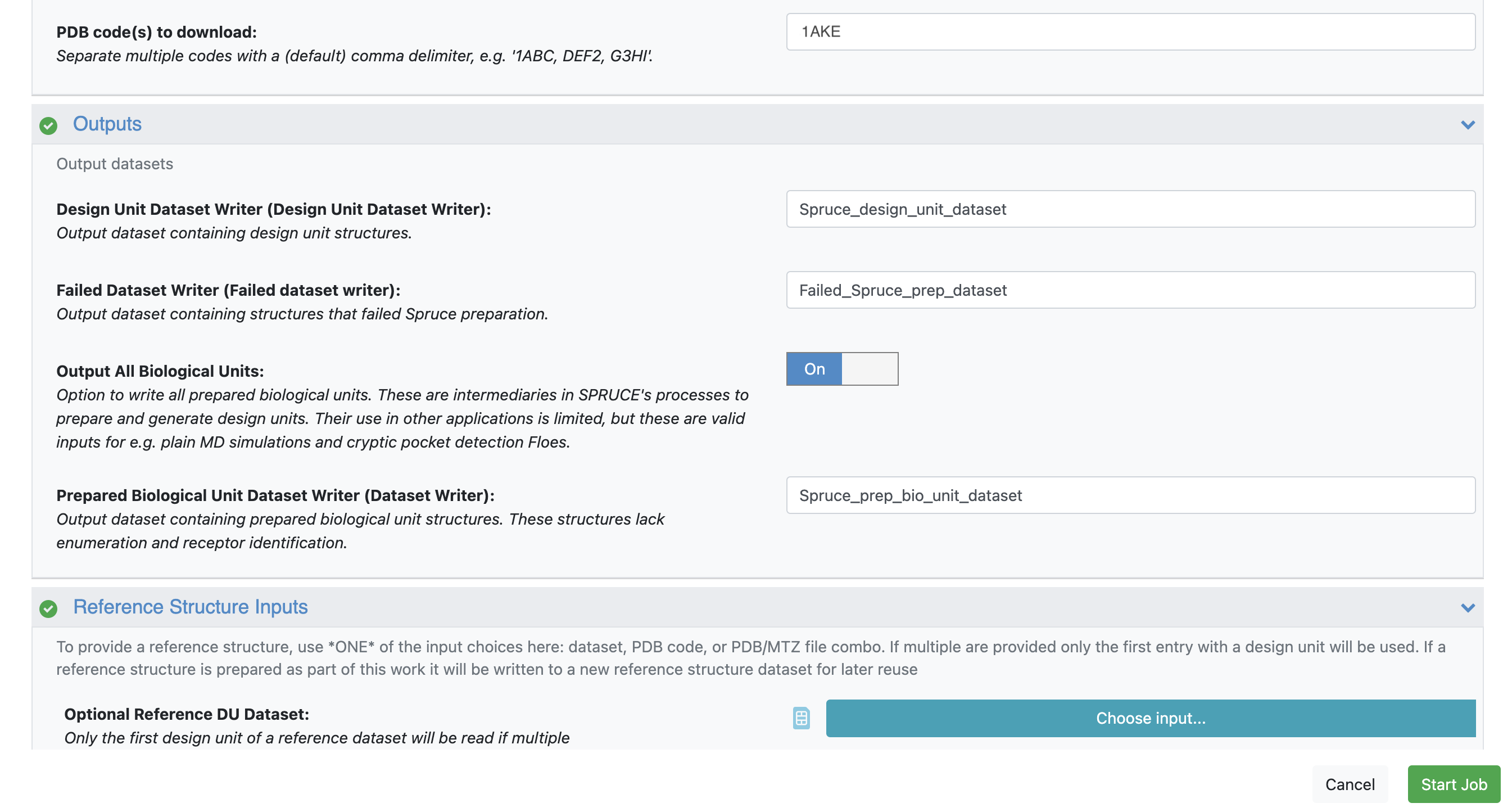
Figure 1. For both 1AKE and 4AKE, toggle the Output All Biological Units parameter On.
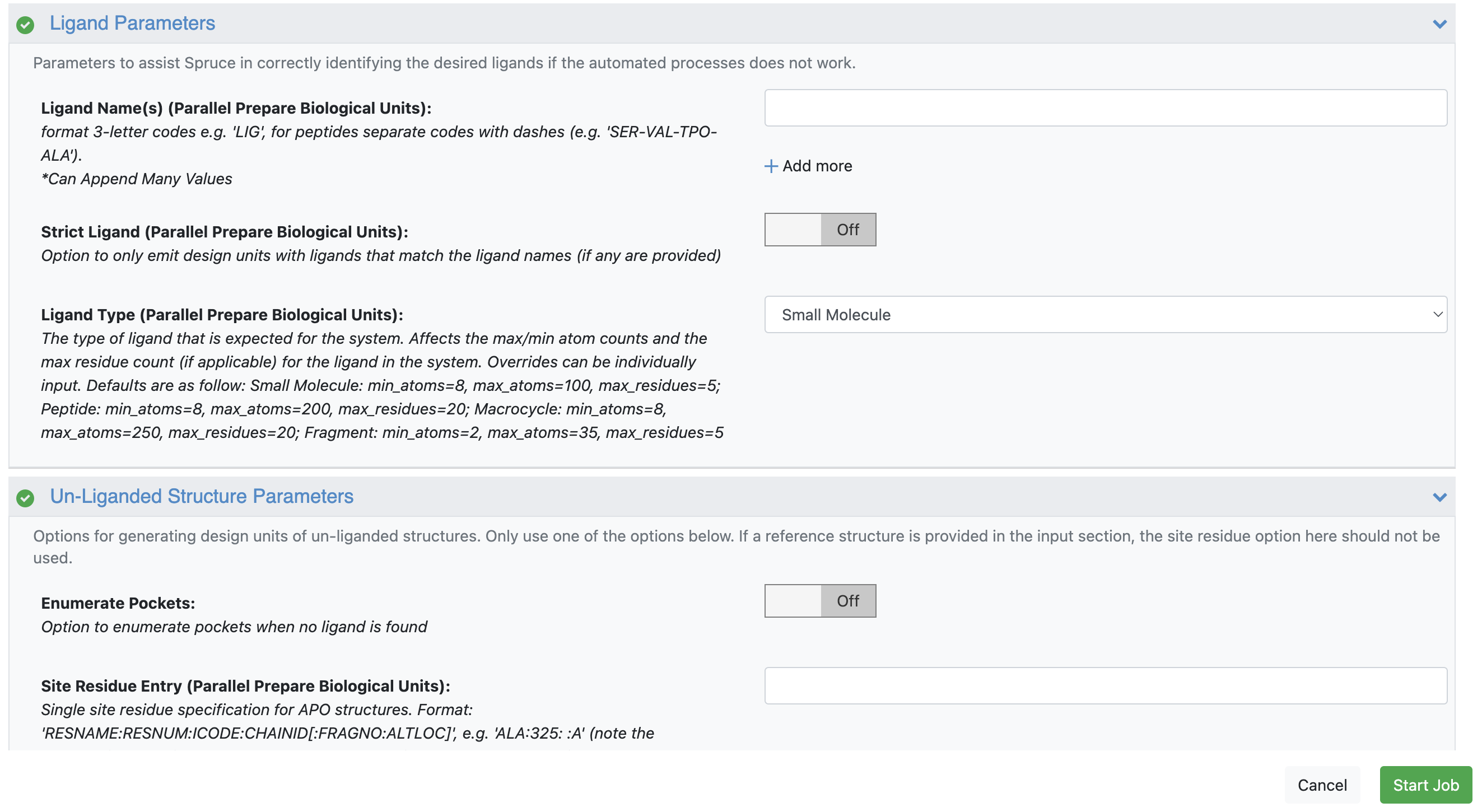
Figure 2. For 1AKE, keep Enumerate Pockets toggled off; for 4AKE, toggle it on.
In your specified output folder on the Data page, click the “+” sign next to the Spruce_design_unit_dataset and Spruce_prep_bio_unit_dataset output datasets to activate and view them in the 3D & Analyze page.
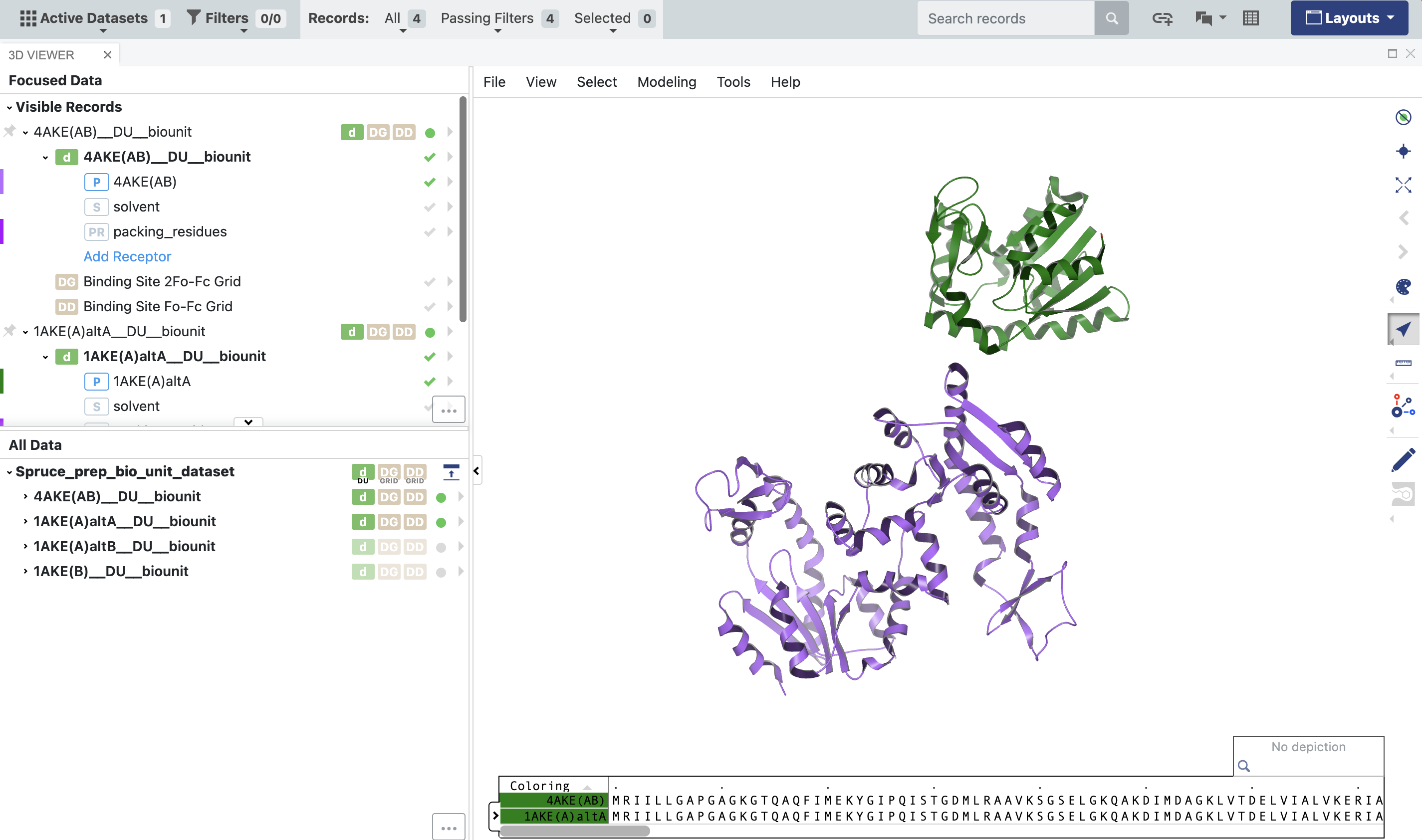
Figure 3. The output of the 1AKE and 4AKE structures from the SPRUCE - Protein Preparation Floe. The Biounit datasets are used downstream in the structural biology floes”
The parentheticals in the names of the records show that the 4AKE DU is a homodimer: it consists of two copies of the same protein with two chains, named “A” and “B.” On the other hand, the 1AKE DU is a monomer consisting only of chain “A.” To better compare the two structures, the Subset Design Unit Floe will allow you to retain chain A of 4AKE and eliminate chain B. From the Workfloes tab on the Floe page, launch this floe to bring up the Job Form.
Inputs: In the Input Design Unit parameter, select the Spruce_design_unit_dataset from the output of the SPRUCE - Protein Preparation Floe for 4AKE.
Ouputs:
Components to keep in the subset: remove everything except protein.
Delete Molecule Components: input: “.*:.*:.*:B” (everything in Chain B).
Click the “Start Job” button.
When you view these DUs in the 3D & Analyze page, you’ll notice that 4AKE and 1AKE are in different frames of reference; though they are crystal structures of the same protein, they are not superposed. This will become important later.
Prepare the X-ray Crystal Structure Density Files
Next, you need to prepare the X-ray crystallographic structure factors for use in the Structural Biology Floes.
On the RCSB PDB deposition page for each structure, under the ‘Download Files’ drop-down, select Validation 2fo-fc coefficients (CIF - gz) to download the structure factors for the 2Fo-Fc density for each deposition. Unpack these .cif.gz files to .cif files, then upload the .cif files to a folder on Orion.
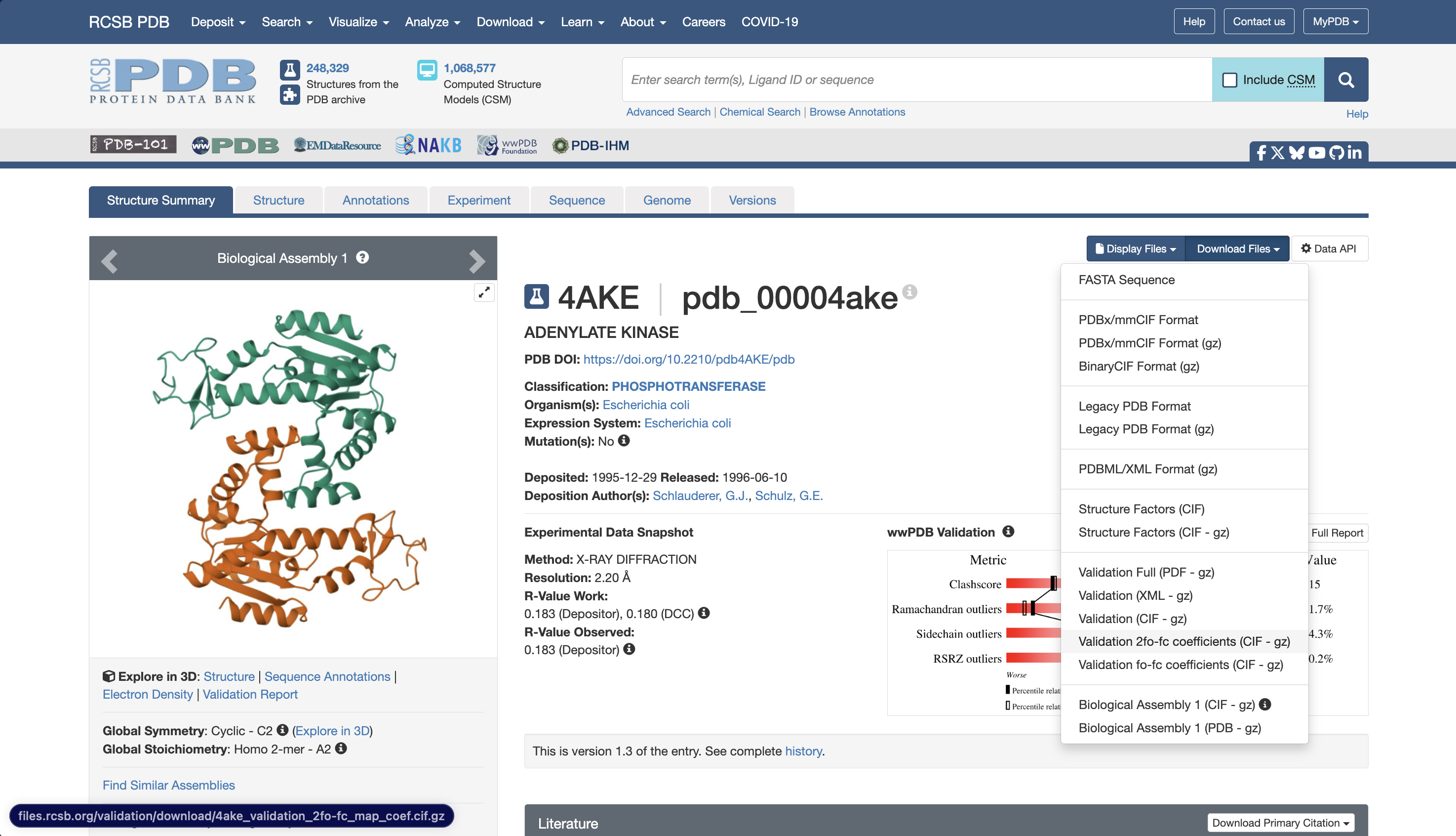
Figure 4. The RCSB entry for 4AKE showing where to download the validation 2fo-fc .cif.gz file.
Because the two structures are in different reference frames, you will need to pick one protein to serve as the reference, then map both structures and densities around that reference structure. For this tutorial, prepare the structures and densities with the open state (4AKE) as a reference.
The Process X-ray Crystal Structures and Densities Floe can be utilized in two different ways:
It can be used to map the density from a structure factor file onto a reference structure.
It can be used to superpose a fit protein structure onto a reference protein structure and use the same transformation to map the fit density from a structure factor file onto the reference protein’s reference frame.
In both cases, the floe outputs:
A dataset containing the transformed/superimposed protein structure and a density grid which can be visually inspected to confirm accurate mapping of both the fit structure and density.
An .mrc file of the density grid from the structure factors, mapped around the protein.
Navigate to the Floe page and launch the Process X-ray Crystal Structures and Densities Floe.
Start with producing the density .mrc file for 4AKE:
Input: For the Reference Dataset, select the SubsetDesignUnits dataset you prepared in the Subset Design Unit Floe.
Reference Mode: For the Reference Density File, select the 2fo-fc validation .cif file you uploaded for 4AKE.
Density Grid Buffer Size: Input 20 to add a 20 Å buffer around the protein.
Density Isosurface Level: Input 1.5 to set all density values below 1.5 sigma to zero.
Click the “Start Job” button to begin the floe.
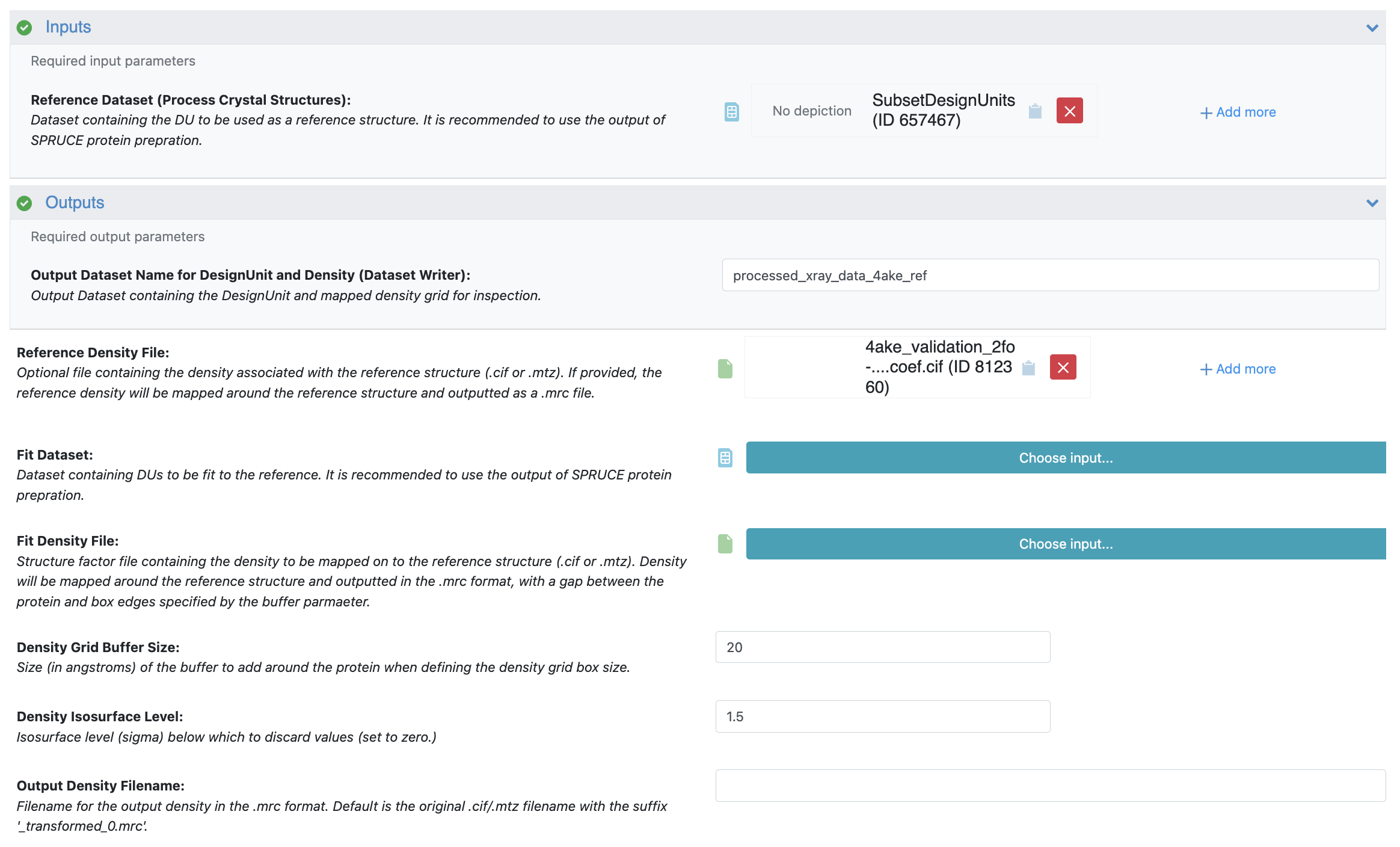
Figure 5. The Job Form for 4AKE in the Process X-ray Crystal Structures and Densities Floe.
The next step is to map the structure and the density from the structure factors for 1AKE onto the reference structure (4AKE).
Input: For the Reference Dataset, select the SubsetDesignUnits dataset you prepared in the Subset Design Unit Floe.
Fit Mode:
Fit Dataset: Select the Spruce_prep_bio_unit_dataset output dataset you prepared earlier for 1AKE.
Fit Density File: Select the 2fo-fc validation .cif file you uploaded for 1AKE.
Density Grid Buffer Size: Input 20 to add a 20 Å buffer around the protein.
Density Isosurface Level: Input 1.5 to set all density values below 1.5 sigma to zero.
Click the “Start Job” button.
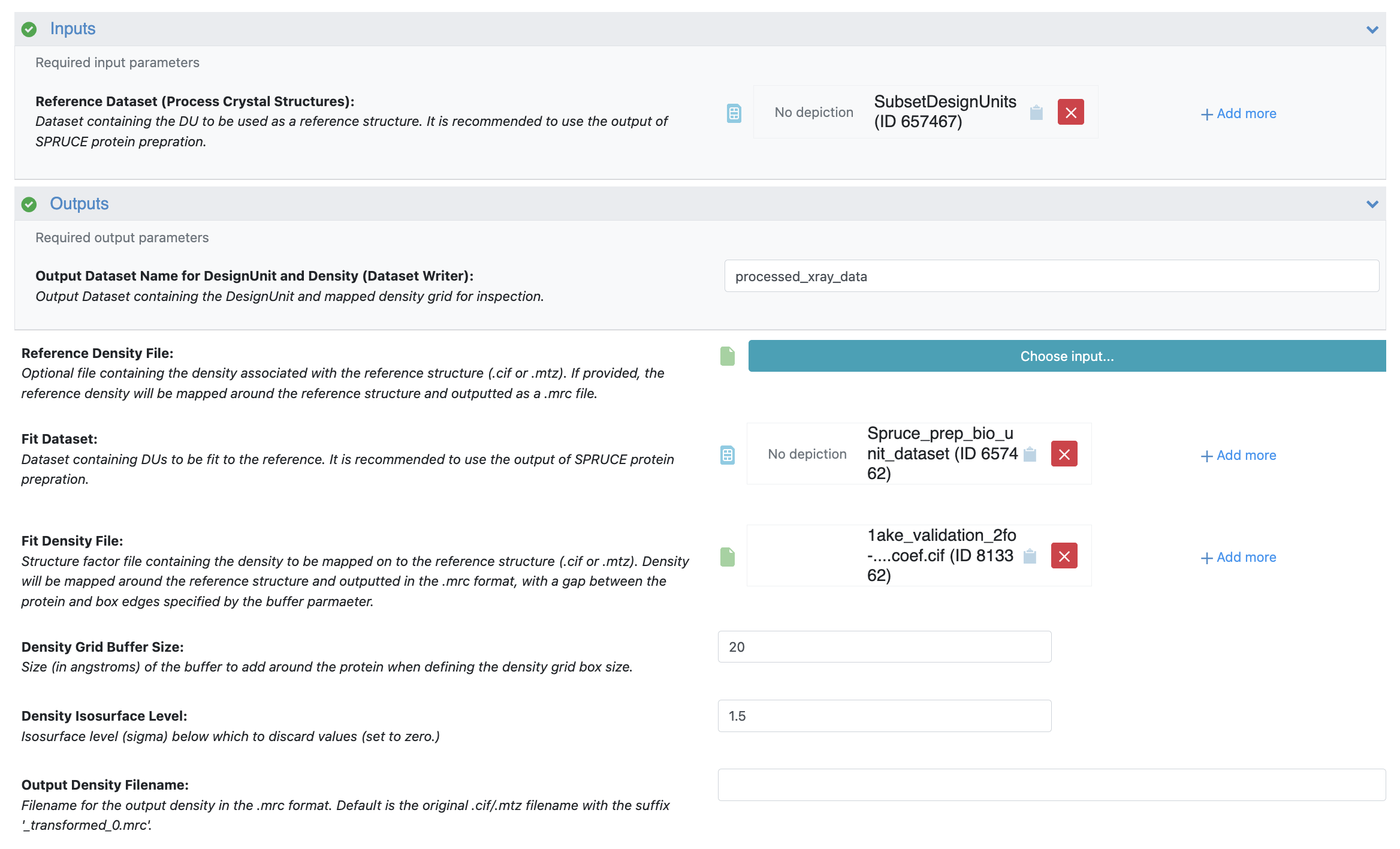
Figure 6. The Job Form for 1AKE in the Process X-ray Crystal Structures and Densities Floe.
Inspect both of the output datasets in the 3D & Analyze page to confirm that the superposition is acceptable, and the densities appear to be mapped correctly. In the 3D & Analyze page:
Expand each dataset.
Click the checkmark next to the density grid to enable it in the 3D Viewer.
Click the arrow next to the density grid, click the concentric circles to add a new contour, and add an isosurface at a level of 2.0 (2 sigma) using a color of your choice.
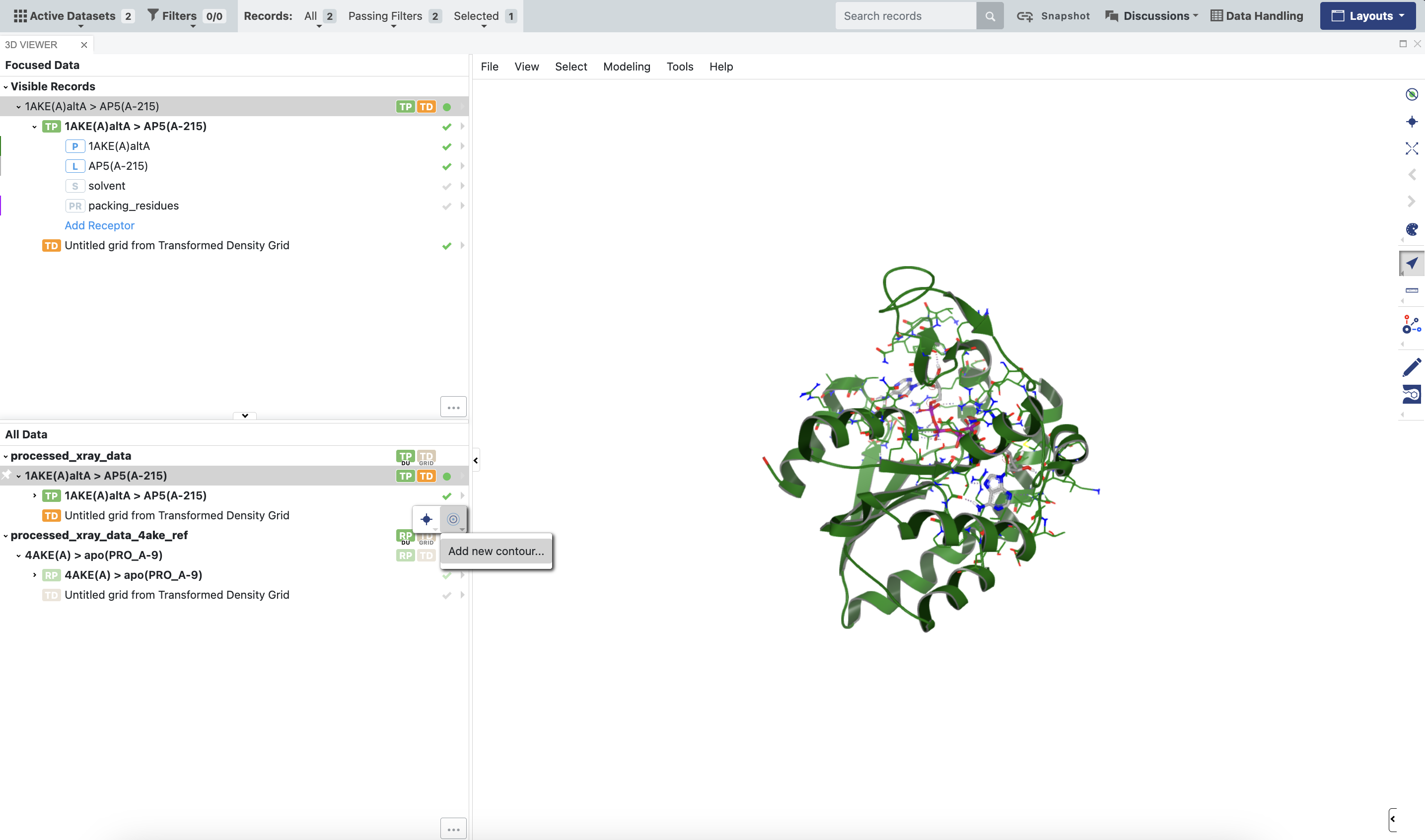
Figure 7. How to set a contour value for viewing density grids outputted by the floe.
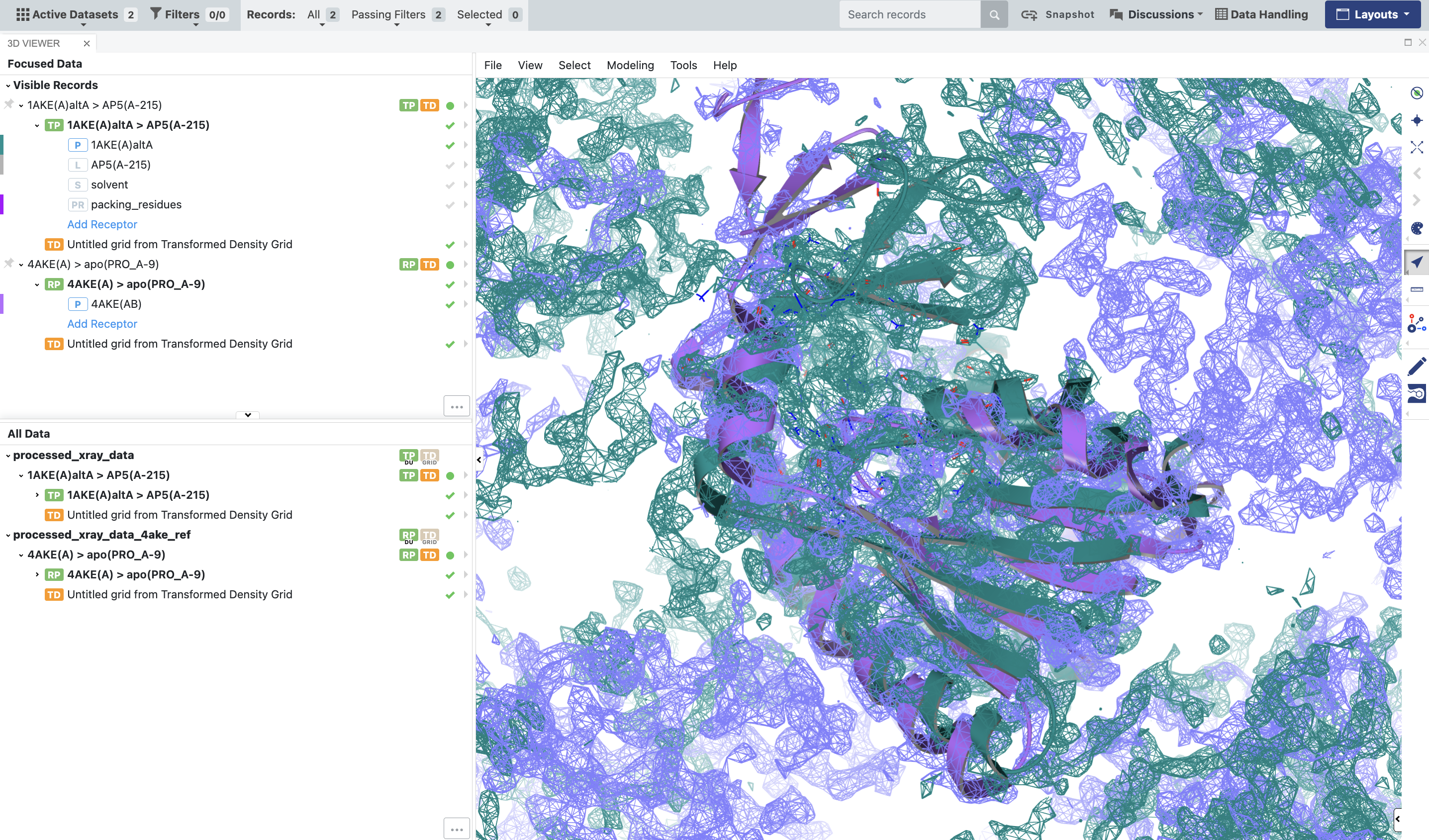
Figure 8. The BioDU for 1AKE should be properly superposed on 4AKE, and the densities should be aligned with the corresponding proteins.
For the next steps, please follow the instructions in the Basic Tutorial 1: Automated WEMD Simulation and Best Structure Search Guided by Target Cryo-EM Map.
Prepare the System for Simulation
Once the X-ray densities are prepared, use the Solvate and Equilibrate Target Protein Floe from the Cryptic Pocket Detection package to prepare the protein for simulation.
Preliminary Structural Biology Floes Run
Once the system is solvated and equilibrated, run the Automated WEMD Simulation and Best Structure Search Guided by Target CryoEM Map Floe, with the density files that were produced by the Process X-ray Crystal Structures and Densities Floe.
What to Expect in Longer Runs
In shorter preliminary runs, if you are starting from a structure that does not align well with the density from another deposition, expect the RSCC to be quite low, close to zero. In longer continuation runs, you can expect that the simulation will sample more structures that are consistent with the density from 1AKE. The floe will output these structures for your inspection in the best_structures_dataset.
Using the Generate Most Probable Path from WEMD Simulation Floe, you can also generate the most probable path from the starting structure to the structure most consistent with the map from 1AKE, if you are interested in the most likely transition pathway between the two structures.
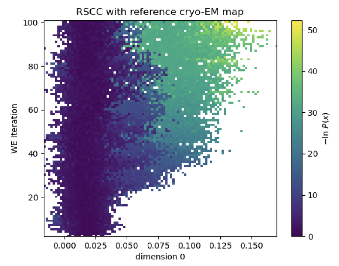
Figure 9. In a 100-iteration simulation, the simulation explores more conformations consistent with the density map from 1AKE.
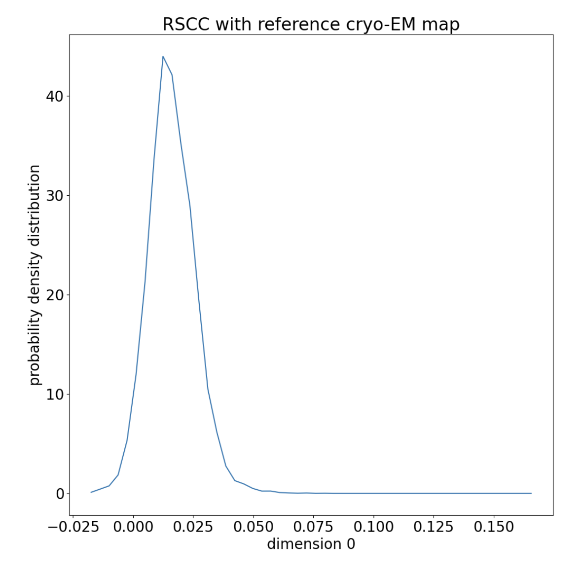
Figure 10. The distribution of RSCCs is normal around the starting RSCC, with a long tail.
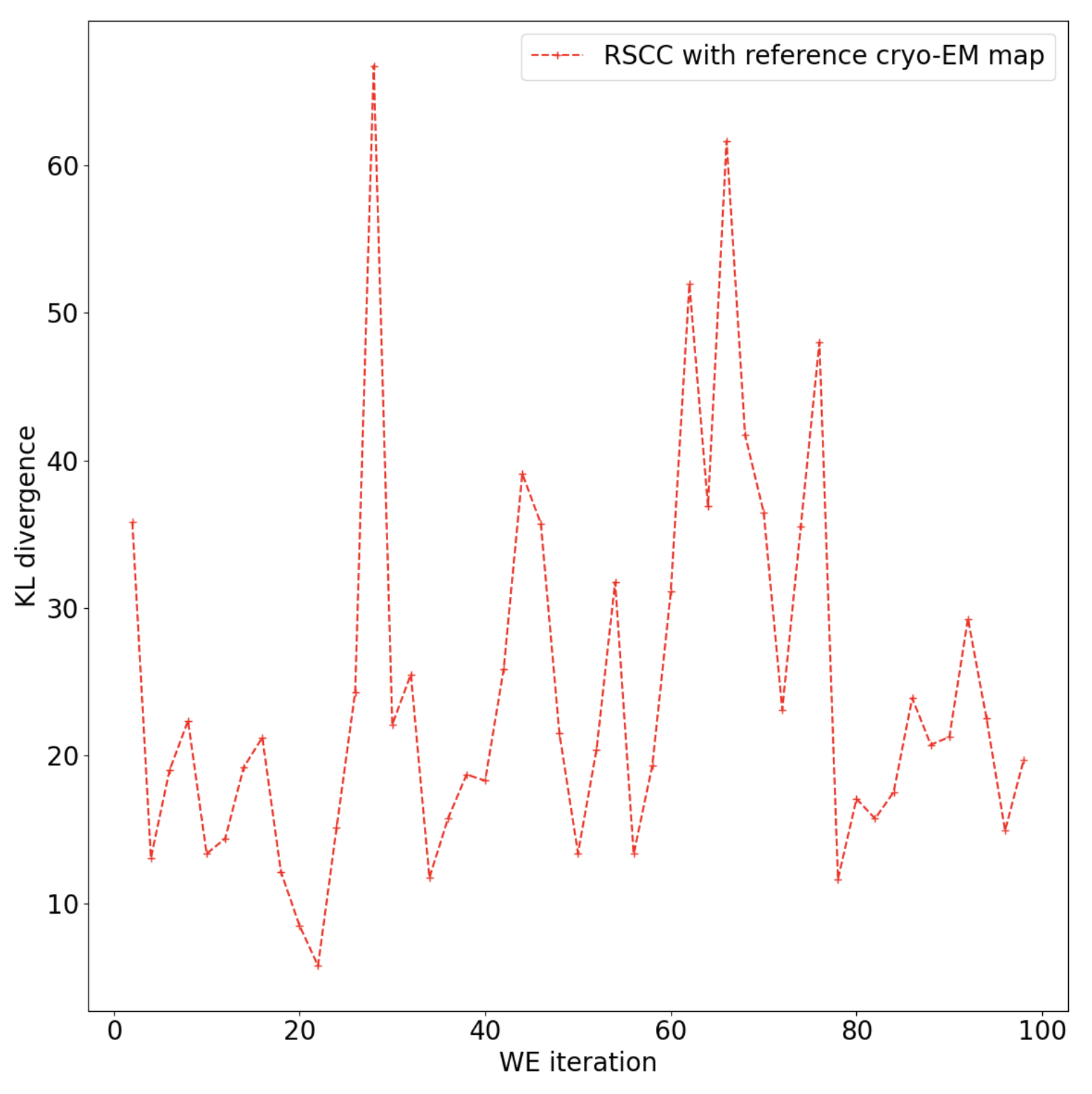
Figure 11. The KL-divergence indicates that the floe has not yet fully converged on a stable distribution and you may want to continue the simulation.
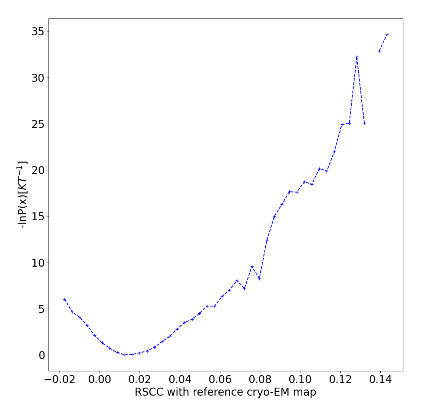
Figure 12. The conditional free energy landscape has a well at the starting structure.