Setting up a Receptor
New DU/Receptor
Use the File->New... menu option to create a new design unit or receptor.
This provides two separate paths to creating a new design unit. Choose the PDB/MMCIF
option to create a design unit starting from a PDB or MMCIF file (with or without an
associated MTZ file). The Molecules option should be used when various molecule
components of the design unit contains in separate files.
Existing DU/Receptor
Use the File->Open Design Unit/Receptor... menu option to open an existing design
unit or receptor. This option allows opening both an OEDU file or a receptor containing
in an OEB or OEB.GZ file.
The HYBRID program requires that a receptor have a bound ligand, while FRED does not. Waters and other crystallographic solvents, that are a aprt of the design unit, are ignored during the docking process of both HYBRID and FRED, unless the user designates them as part of the receptor target. (See the following molecules section).
Note
If a receptor is chosen using File->Open menu option Make Receptor will switch to finish mode to show a summary of the information on the receptor. You can then select any of the setup steps to modify the receptor as desired.
Molecules
|
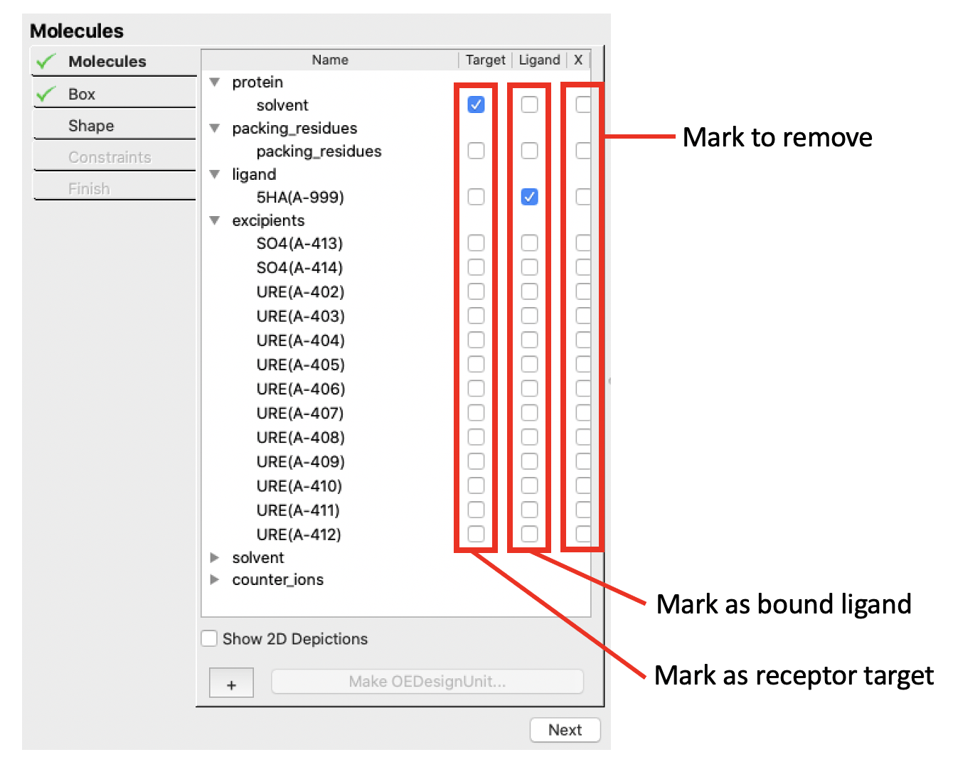
Molecules controls |
The purpose of the molecules workflow stage is to classify molecules. A molecule is a covalently connected set of atoms that is not covalently bound to any other molecule.
Note
Covalently bound ligands are not supported.
Each molecule can have one of three classifications.
Target
These molecules make up the structure of the target (protein) that docking ligands interact with. The structure is treated as rigid during the docking process, except for rotatable hydrogens (e.g., hydroxyls) which are rotated to form optimal hydrogen bonding interactions during the docking process (this rotation is an internal calculation that is reflected in the docked scores, but not in any output structure).
Bound Ligand
This molecule is a ligand bound into the active of the protein. Generally the bound ligand structure is determined by x-ray crystallography, although a docked molecule structure could also be used instead if there is high confidence in the correctness of the docked structure.
This molecule is required by HYBRID during the docking process to guide docking molecules into a docking mode similar to the bound ligand. It is not required by FRED and is ignored by FRED if present.
Excess Molecules
Excess molecule are those that should not be included as part of the design unit. Once a set of molecules are marked to be removed (
X), and design unit is prepared, those molecules are removed from the system.
Molecule classification is done using the Mark as bound ligand, Mark as receptor target, and Mark to remove checkboxes (see the molecule controls figure).
Listed molecules can be identified in the 3D window by clicking their names in the list. Selected molecules are depicted in CPK rather than wireframe mode. Molecule selection can also be done on a molecule in the 3D window to identify which molecule it is in the molecule list.
At least one molecule must be classified as a receptor target molecule before moving on to the next stage of the workflow.
Box
|
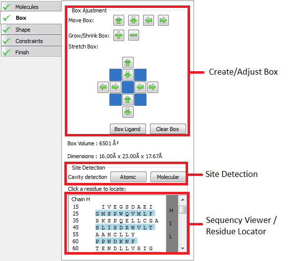
Box controls |
The goal in this stage of the receptor setup workflow is to define a box enclosing the active site. The box should enclose the entire region active site where heavy atoms of the docking ligand can be placed. Any docked pose with any heavy atom that lies outside the box will be rejected.
If a bound ligand was specified in the previous stage a default box will automatically be setup around the bound ligand, otherwise an initial box can be created by clicking on a protein residue in the 3D window.
Once created a box and be adjusted using the Create/Adjust box controls. Clicking on a protein residue will also automatically extend the box to enclose the clicked reside.
Two cavity detection routines are also provided. Both the Atomic and Molecular cavity detection routines create blobs in the 3D windows in the grooves and pockets around the protein that could potentially be active sites. The box can then be extended or created around a blob by clicking on it. The Molecular cavity detection uses a better algorithm, but takes much longer to run than the Atomic detection algorithm. The sensitivity slider adjusts the contour level of created blobs.
The sequence viewer can be used to locate specific residues on the protein. When a residue is clicked in the sequence viewer a label on the corresponding residue is shown in the 3D window.
Shape

|
Shape controls |
The Shape stage of the receptor setup workflow defines the inner and outer contours of the receptor. Both contours are always enclosed by the box setup in the previous stage of the setup workflow.
The “Create Shape” button sets up a shape potential and automatically selects reasonable inner and outer contours (the former is disabled by default, see below). The slider below the “Create Shape” can be used to select the type of shape potential that will be generated when the “Create Shape” button is pushed. If “Favors Protein” is selected the contours will tend to extend closer to the protein before extending out into solvent, while “Favors Solvent” will cause the reverse to happen. Balanced, the default, is reasonable in most cases.
Once the contours are created, their size can be adjusted using the inner and outer contour sliders. The sliders control the inner and outer contour levels (while the slider below the “Create Shape” button controls the underlying potential being contoured). Either contour can be disabled to increase the space of poses searched for each docking ligand.
Disabled is the recommended, and default setting, for the inner contour. The inner contour should be enabled only if the active site is extremely large. In these cases using the inner contour can increase docking speed by ~25% at the cost of reduced docking accuracy.
The outer contour should only be disabled in cases where the active site is flat with no well defined shape. Docking without the outer contour can increase docking time by as much as 100 fold.
Note
In general the outer contour should be between 500 and 2000 cubic Ångströms and the inner contour between 25 and 100 cubic Ångströms.
Constraints
|
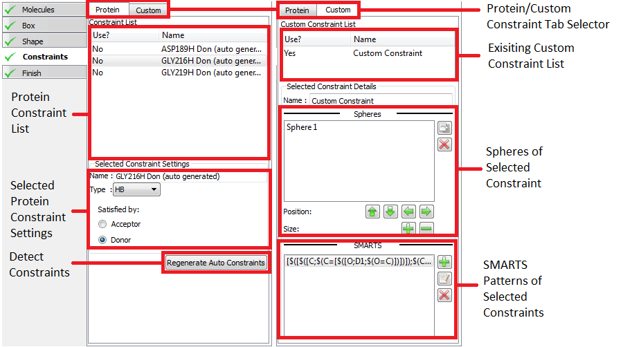
Constraints controls |
Constraints are a way of ensuring that receptor-ligand interactions known to be associated with activity are present in a docked pose. This inclusion of prior knowledge has been shown to be effective in improving the performance for pose prediction and virtual screening of docking programs including FRED [Warren-2006]. While the use of constraints can improve performance it can also degrade performance if the constraints used are not chosen wisely. The current recommended practice is to use the smallest number of constraints possible that describe the interaction associated with activity and to validate that the results generated (poses and virtual screening performance) are an improvement versus using no constraints. For this release, validation must be done using either FRED or HYBRID using a saved receptor file.
Adding constraints to a receptor is optional. Constraints are user specified interactions that docked poses are required to make with the protein. Once created a constraint can be enabled or disabled. A disabled constraint has no effect on the docking process of either FRED or HYBRID. Any docked pose that does not satisfy an enabled constraint will be rejected. If multiple enabled constraints are specified poses must satisfy every one. It is not possible for instance to only require that only 3 out of 4 constraints be satisfied.
There are two types of constraint that can be specified; Protein and Custom constraints. Protein constraints are easy to use constraints that are associated with a particular protein atom and are satisfied when a docked poses makes a specified type of interaction with it (hydrogen bond, metal-chelator or contact). Custom constraints are defined by spheres within the active site and optionally one or more SMARTS patterns. Custom constraints are satisfied when a heavy atom of a docked pose falls with one of the spheres if no SMARTS pattern is satisfied, or when an atom on the docked pose matching one of the SMARTS patterns falls with a sphere.
To edit, view or create protein constraints click on the proteins tab at the top of the window. If the receptor contains a bound ligand, Make Receptor may automatically detect potential constraints. Auto-detected constraints appear in the constraint list like any other protein constraint and are disabled by defaults. To enable them click the Use field next to the constraint you wish to enable in the protein constraint list. To see where the constraint is located in the 3D window and view the constraint setting click on the name of the constraint in the protein constraint list. To create a new protein constraint simple click on a protein atom in the receptor site and use the protein constraint setting to select the type of constraint desired.
To edit, view or create custom constraints select the custom tab at the top of the window. Select and edit custom constraints by clicking on their name in the custom constraint list. To create a new constraint click on an atom in the 3D window, which will create an initial sphere around the clicked atom and prompt you to name the constraint. To add SMARTS patterns click on the + button in the “SMARTS Pattern of Selected Constraint” list. As with protein constraints they can be enabled and disabled by clicking the Use column next to the constraint name.
Finish
|
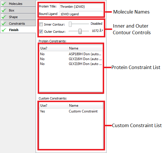
Finish controls |
This stage of the workflow provides a summary of the information stored on the receptor. You should now save your receptor using either the button at the bottom of the screen or the File->Save menu option.
If you load a receptor using the File->Open menu option, the Make Receptor will automatically load all the receptor information at set the workflow to this stage.
To edit any part of the receptor click on the appropriate workflow mode button on the left (e.g., Molecules, Box, Shape or Constraints).